7. AIR CONDITIONER
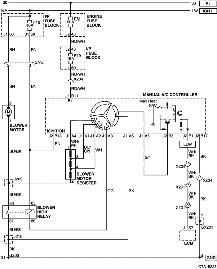
1) AIR CONDITIONER CONTROL SWITCH & BLOWER MOTOR CIRCUIT
a. CONNECTOR INFORMATION
CONNECTOR NO
(PIN NO, COLOR) |
CONNECTING WIRING HARNESS |
CONNECTOR POSITION |
| X101 (36 Pin, Black)
|
Engine - Body |
Behind the Engine Fuse Block |
| X201 (92 Pin, Black) |
Body - I.P |
Below to the "A" pillar |
| X204 (16 Pin, Black) |
I.P - FATC |
Behind the FATC |
| GX201 (Black/Gray) |
I/P |
Behind Steering Column - Lower |
| G203 |
FATC |
Inside the left instrument panel |
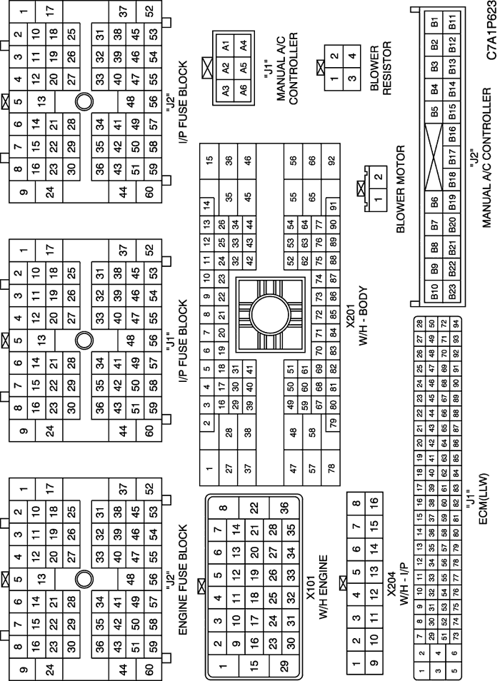
b. CONNECTOR IDENTIFICATION SYMBOL & PIN NUMBER POSITION
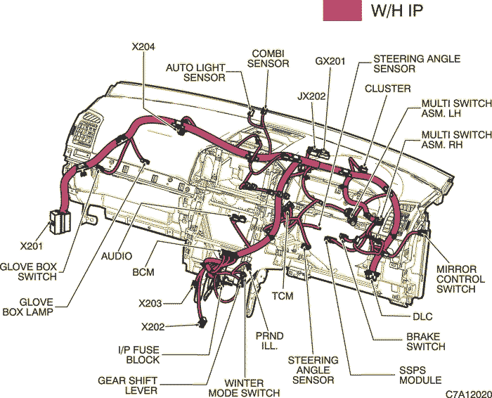
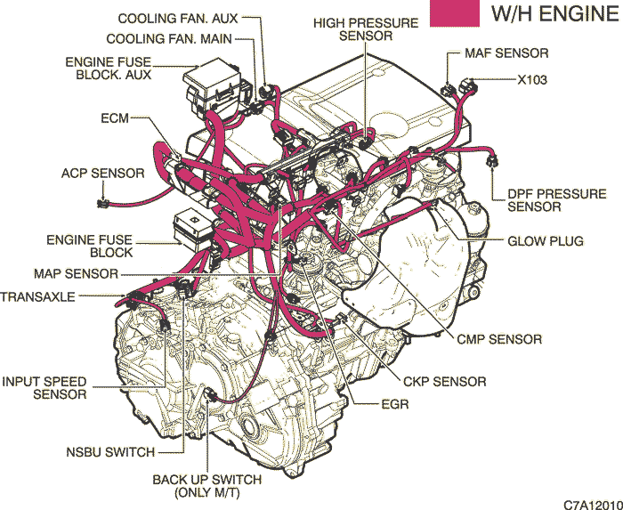
c. POSITION OF CONNECTORS AND GROUNDS
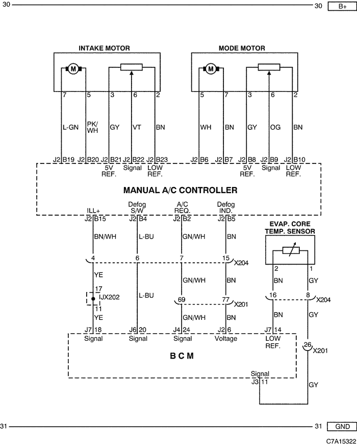
2) INTAKE MOTOR, MODE MOTOR & EVAP CORE TEMP. SENSOR CIRCUIT
a. CONNECTOR INFORMATION
CONNECTOR NO
(PIN NO, COLOR) |
CONNECTING WIRING HARNESS |
CONNECTOR POSITION |
| X201 (92 Pin, Black) |
Body - I.P |
Below to the "A" pillar |
| X204 (16 Pin, Black) |
I.P - FATC |
Behind the FATC |
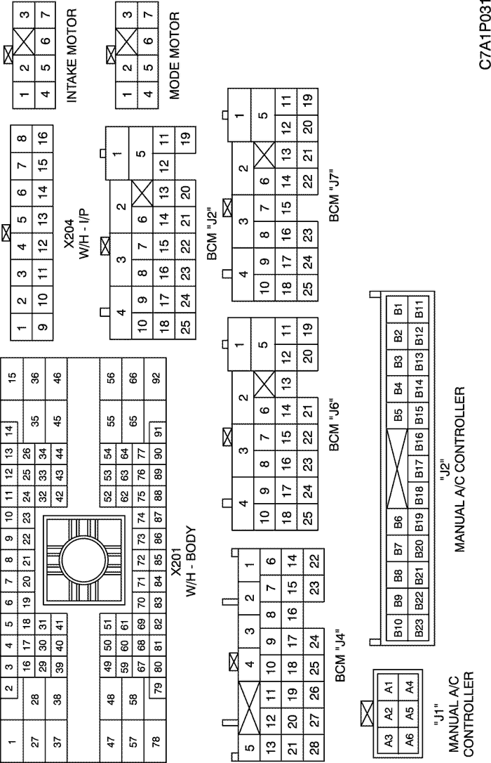
b. CONNECTOR IDENTIFICATION SYMBOL & PIN NUMBER POSITION
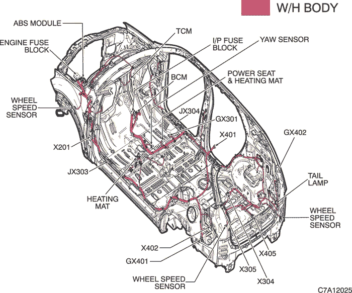
c. POSITION OF CONNECTORS AND GROUNDS
d. SPLICE PACK
| © Copyright Chevrolet Europe. All rights reserved |