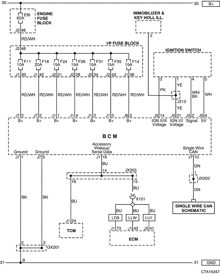
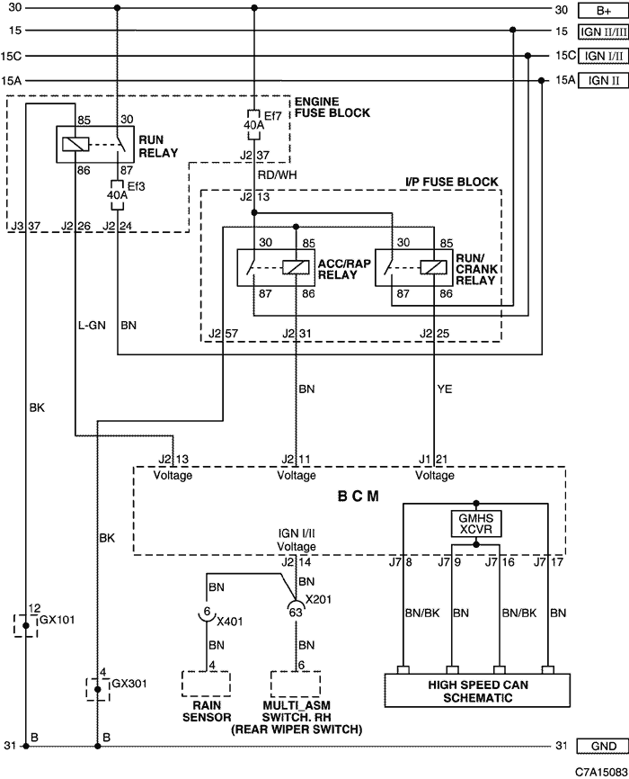
6. BCM (BODY CONTROL MODULE)
1) POWER SUPPLY, GROUND, IGNITION SWITCH CIRCUIT
a. CONNECTOR INFORMATION
CONNECTOR NO
(PIN NO, COLOR) |
CONNECTING WIRING HARNESS |
CONNECTOR POSITION |
| X101 (36 Pin, Black)
|
Engine - Body |
Behind the Engine Fuse Block |
| X201 (92 Pin, Black) |
Body - I.P |
Below to the "A" pillar |
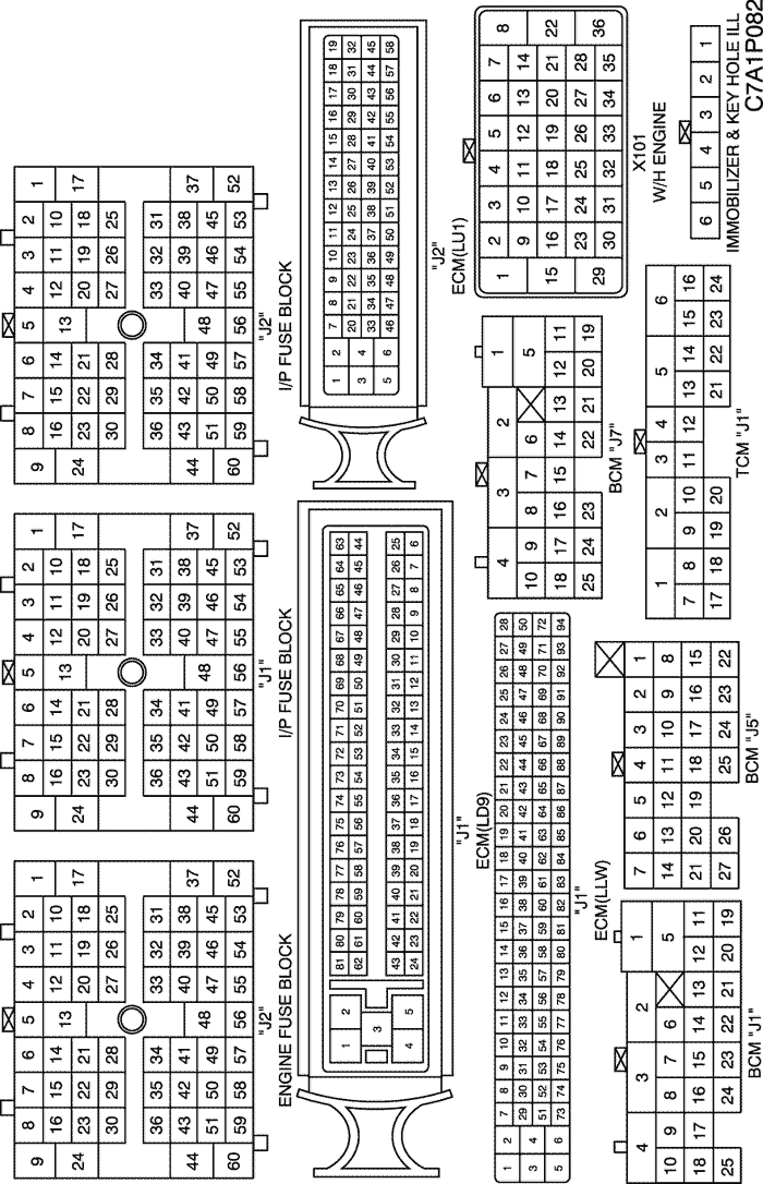
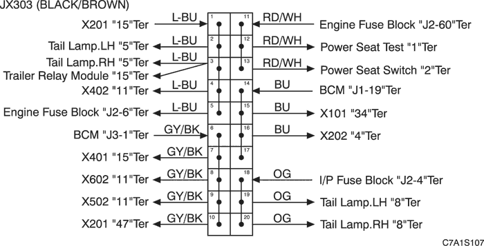
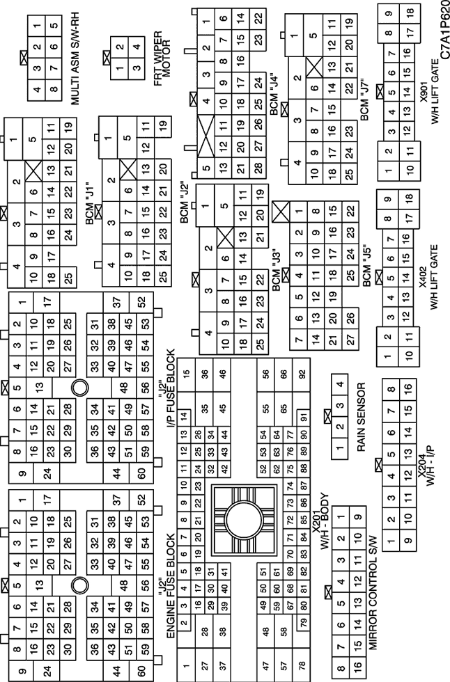
b. CONNECTOR IDENTIFICATION SYMBOL & PIN NUMBER POSITION
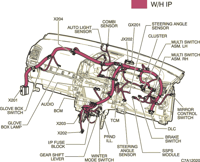
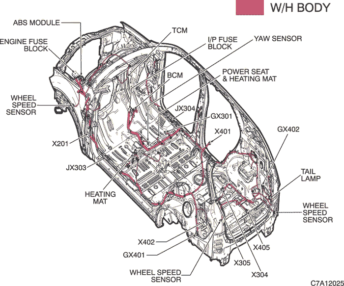
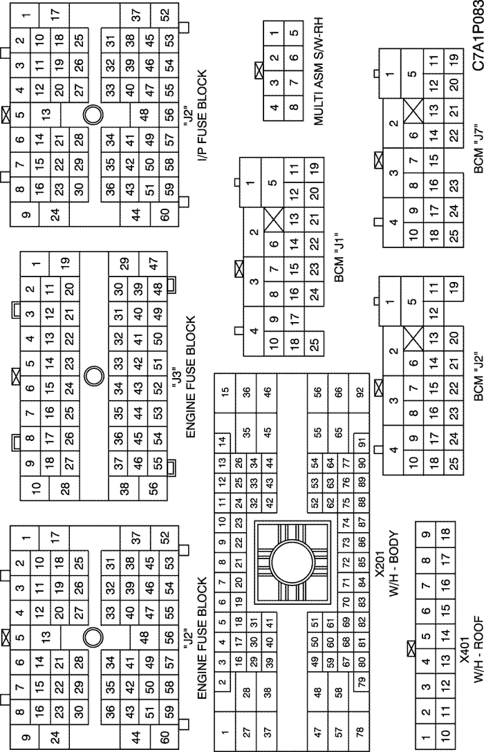
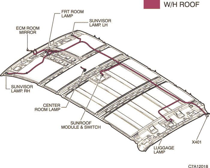
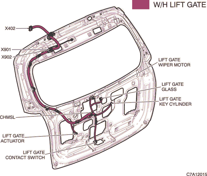
c. POSITION OF CONNECTORS AND GROUNDS
d. SPLICE PACK
2) POWER MODE, RAIN SENSOR & REAR WIPER SWITCH CIRCUIT
a. CONNECTOR INFORMATION
CONNECTOR NO
(PIN NO, COLOR) |
CONNECTING WIRING HARNESS |
CONNECTOR POSITION |
| X201 (92 Pin, Black) |
Body - I.P |
Below to the "A" pillar |
| X401 (18 Pin, Colorless) |
Roof - Body |
Inside the left "C" pillar |
| GX101 (Black/Gray) |
Front |
Behind the left HeadLamp |
| GX301 (Black/Gray) |
Body |
Under the right seat cushion |
b. CONNECTOR IDENTIFICATION SYMBOL & PIN NUMBER POSITION
c. POSITION OF CONNECTORS AND GROUNDS
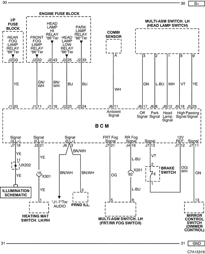
3) HEAD LAMP, ILLUMINATION, FRONT/REAR FOG, BRAKE SWITCH & DIMMER CONTROL CIRCUIT
a. CONNECTOR INFORMATION
CONNECTOR NO
(PIN NO, COLOR) |
CONNECTING WIRING HARNESS |
CONNECTOR POSITION |
| X201 (92 Pin, Black) |
Body - I.P |
Below to the "A" pillar |
| X301 (12 Pin, Colorless) |
Console - Body |
Below the floor console |
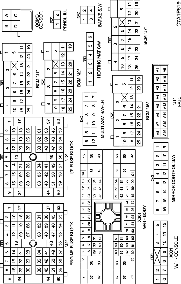
b. CONNECTOR IDENTIFICATION SYMBOL & PIN NUMBER POSITION
c. POSITION OF CONNECTORS AND GROUNDS
d. SPLICE PACK
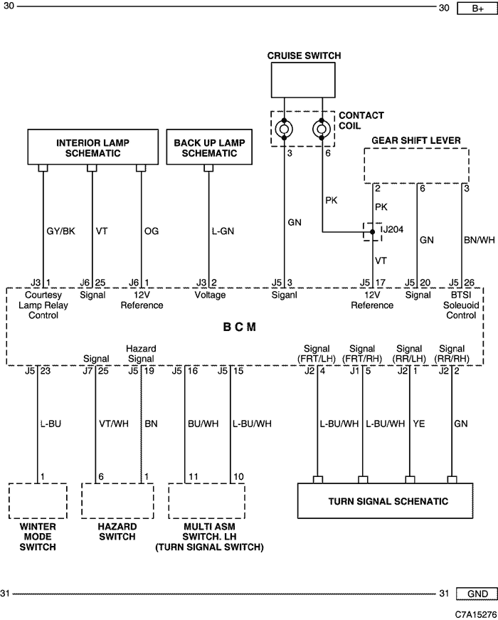
4) INTERIOR LAMP, BACK UP LAMP, GEAR SHIFT LEVEL, SWITCH(WINTER MODE, CRUISE, HAZARD, TURN SIGNAL) CIRCUIT
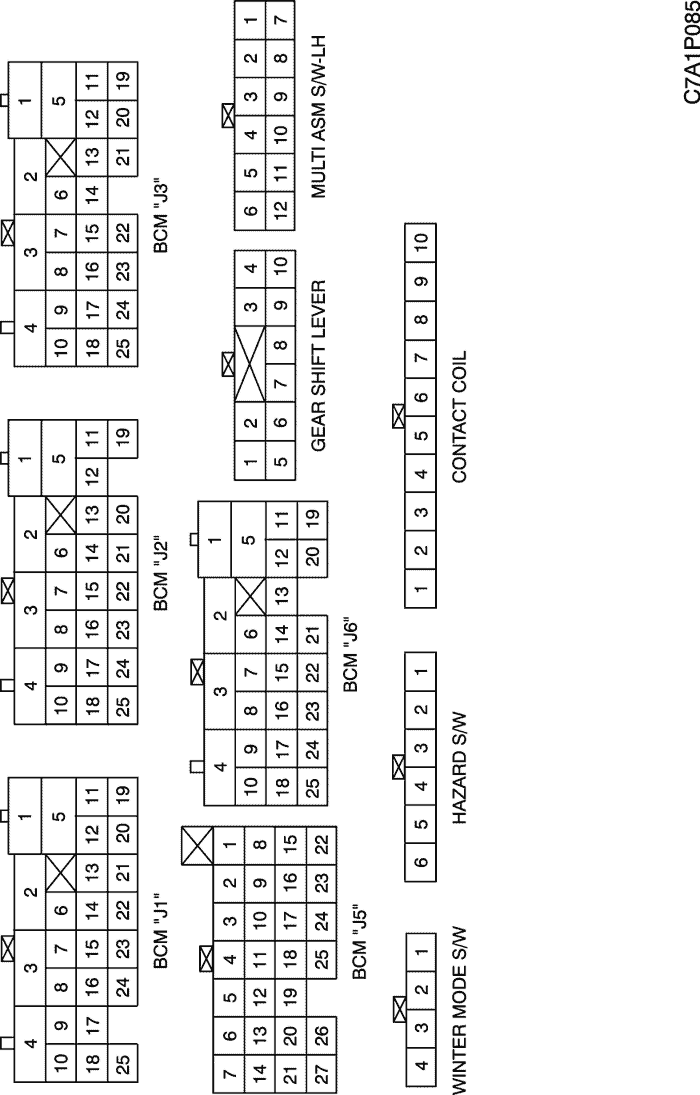
b. CONNECTOR IDENTIFICATION SYMBOL & PIN NUMBER POSITION
c. POSITION OF CONNECTORS AND GROUNDS
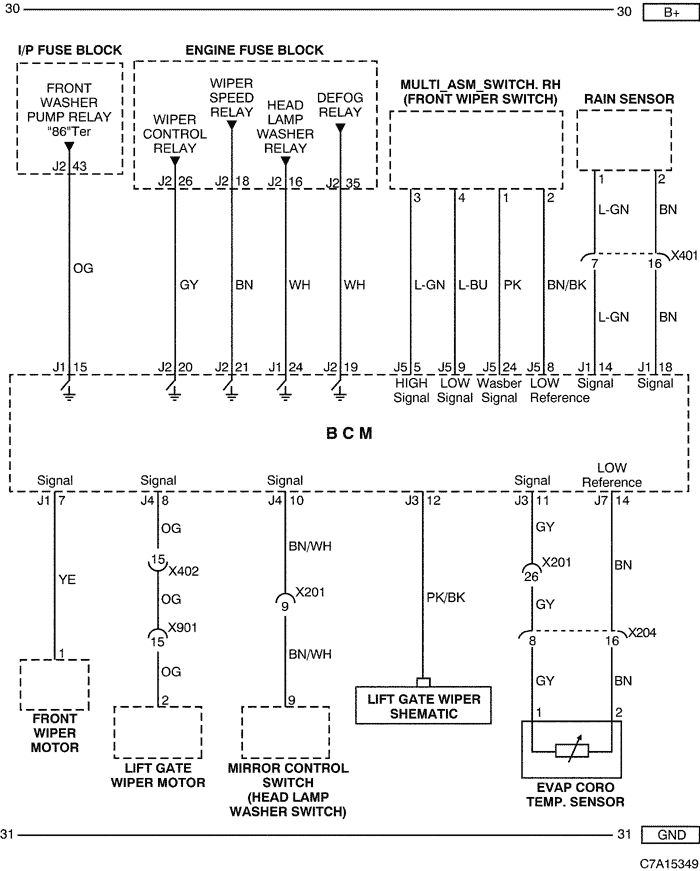
5) FRONT WIPER, LIFT GATE WIPER, RAIN SENSOR & EVAP CORE TEMP. SENSOR CIRCUIT
a. CONNECTOR INFORMATION
CONNECTOR NO
(PIN NO, COLOR) |
CONNECTING WIRING HARNESS |
CONNECTOR POSITION |
| X201 (92 Pin, Black) |
Body - I.P |
Below to the "A" pillar |
| X204 (16 Pin, Black) |
I.P - FATC |
Behind the FATC |
| X401 (18 Pin, Colorless) |
Roof - Body |
Inside the left "C" pillar |
| X402 (18 Pin, Colorless) |
Lift Gate - Body |
Behind the left "C" pillar |
| X901 (18 Pin, Colorless) |
Lift Gate - Lift Gate JPR |
Behind the "2nd" Seat |
b. CONNECTOR IDENTIFICATION SYMBOL & PIN NUMBER POSITION
c. POSITION OF CONNECTORS AND GROUNDS
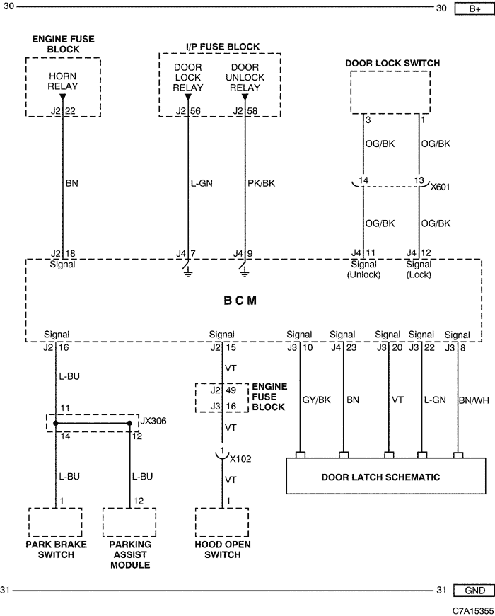
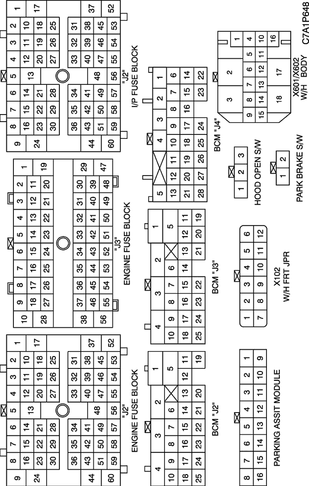
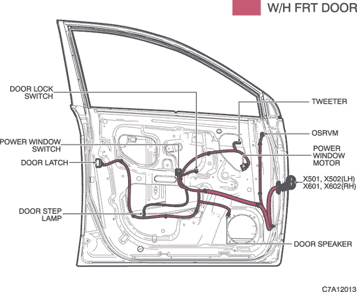
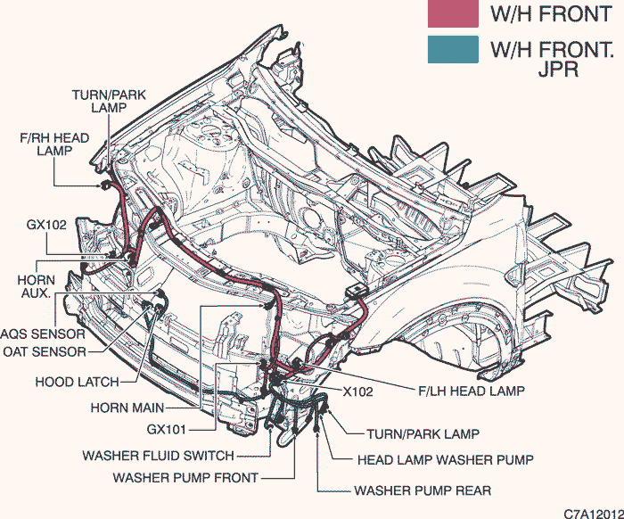
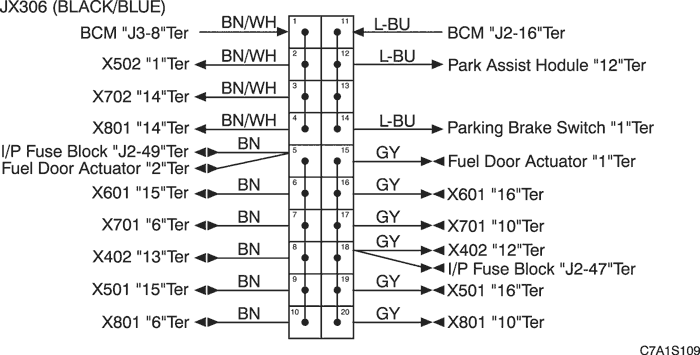
6) DOOR LOCK/UNLOCK, HORN, DOOR LATCH, PARKING ASSIST & SWITCH (PARK BRAKE,HOOD OPEN, DOOR LOCK) CIRCUIT
a. CONNECTOR INFORMATION
CONNECTOR NO
(PIN NO, COLOR) |
CONNECTING WIRING HARNESS |
CONNECTOR POSITION |
| X102 (12 Pin, Black) |
Front JPR - Front |
Behind the left side Head Lamp |
| X601 (18 Pin, Gray) |
Body - Front RH Door |
Under the right "A" Pillar |
b. CONNECTOR IDENTIFICATION SYMBOL & PIN NUMBER POSITION
c. POSITION OF CONNECTORS AND GROUNDS
d. SPLICE PACK
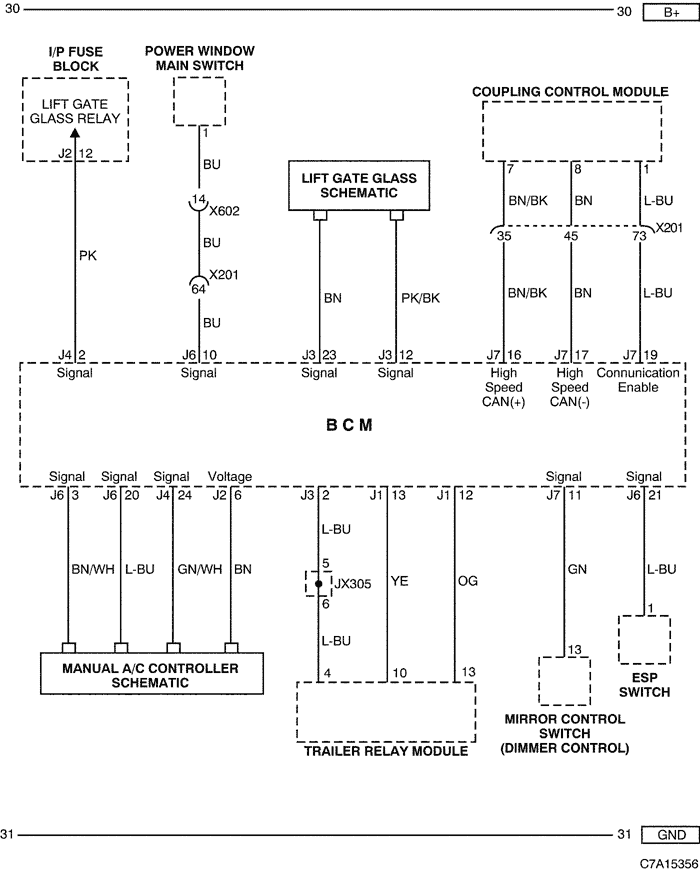
7) POWER WINDOW, LIFT GATE GLASS, COUPLING CONTROL MODULE, ESP SWITCH & MANUAL A/C CONTROLLER CIRCUIT
a. CONNECTOR INFORMATION
CONNECTOR NO
(PIN NO, COLOR) |
CONNECTING WIRING HARNESS |
CONNECTOR POSITION |
| X201 (92 Pin, Black) |
Body - I.P |
Below to the "A" pillar |
| X602 (18 Pin, Colorless) |
Body - Front RH Door |
Under the right "A" Pillar |
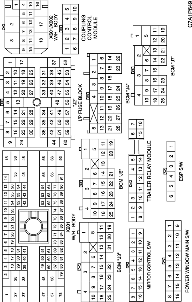
b. CONNECTOR IDENTIFICATION SYMBOL & PIN NUMBER POSITION
c. POSITION OF CONNECTORS AND GROUNDS
d. SPLICE PACK
| © Copyright Chevrolet Europe. All rights reserved |