SECTION 5
ELECTRICAL WIRING DIAGRAMS
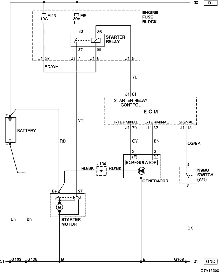
1. STARTING & CHARGING SYSTEM
1) BATTERY, STARTER MOTOR, GENERATOR & NSBU SWITCH CIRCUIT : FAM II 2.4D (LD9)
a. CONNECTOR INFORMATION
CONNECTOR NO
(PIN NO, COLOR) |
CONNECTING WIRING HARNESS |
CONNECTOR POSITION |
| G103 |
Battery |
Behind the Engine Fuse Block |
| G105 |
Battery |
On the Cylinder Block |
| G108 |
Engine (FAM II) |
On the Cylinder Block |
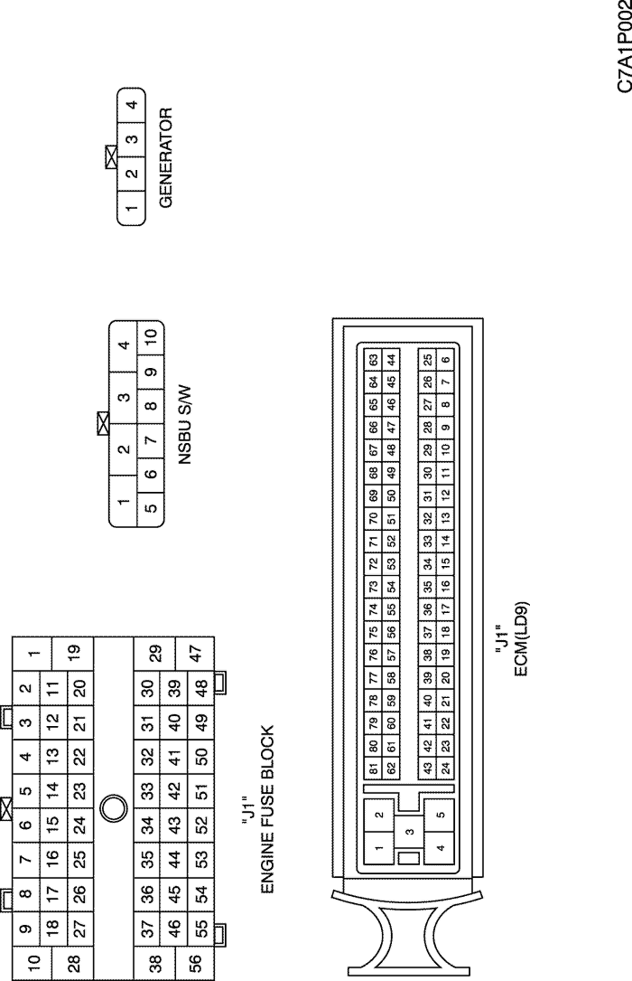
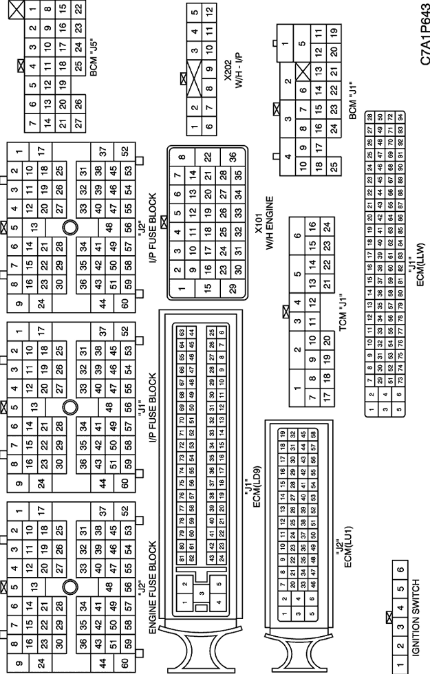
b. CONNECTOR IDENTIFICATION SYMBOL & PIN NUMBER POSITION
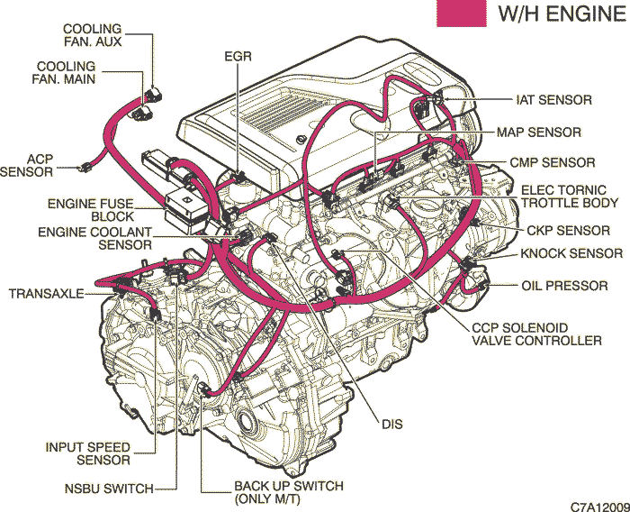
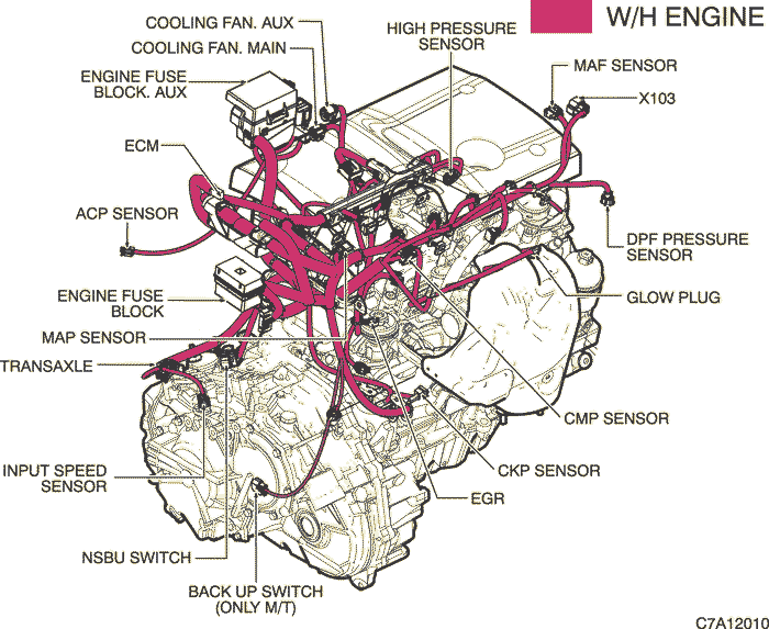
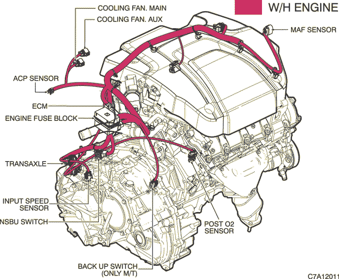
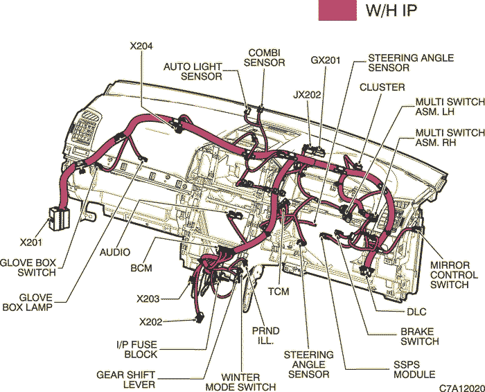
c. POSITION OF CONNECTORS AND GROUNDS
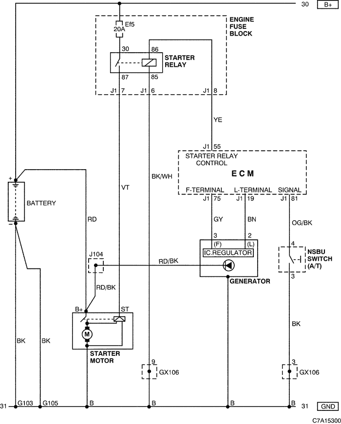
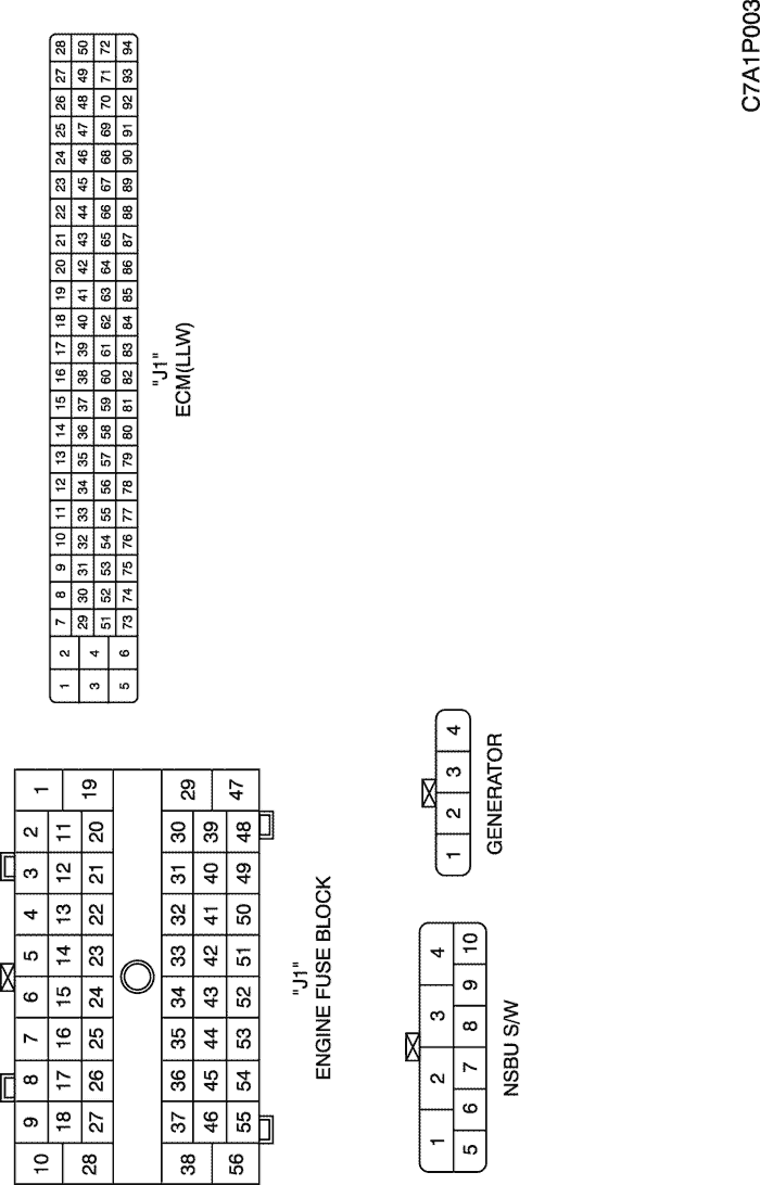
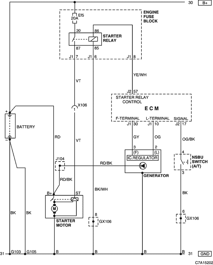
2) BATTERY, STARTER MOTOR, GENERATOR & NSBU SWITCH CIRCUIT : 2.0 DIESEL (LLW)
a. CONNECTOR INFORMATION
CONNECTOR NO
(PIN NO, COLOR) |
CONNECTING WIRING HARNESS |
CONNECTOR POSITION |
| G103 |
Battery |
Behind the Engine Fuse Block |
| G105 |
Battery |
On the Cylinder Block |
| GX106 (Black/Gray) |
Engine (DSL/HFV6) |
Upper the Cylinder Head |
b. CONNECTOR IDENTIFICATION SYMBOL & PIN NUMBER POSITION
c. POSITION OF CONNECTORS AND GROUNDS
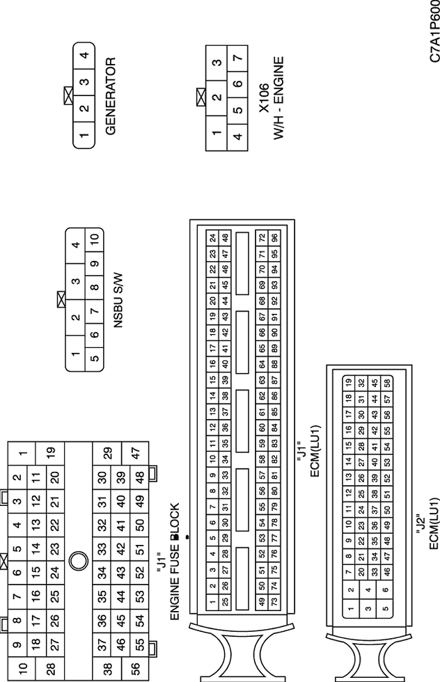
3) BATTERY, STARTER MOTOR, GENERATOR & NSBU SWITCH CIRCUIT : HFV6 3.2 (LU1)
a. CONNECTOR INFORMATION
CONNECTOR NO
(PIN NO, COLOR) |
CONNECTING WIRING HARNESS |
CONNECTOR POSITION |
| X106 (7 Pin, Black) |
Engine - Fuel Injector (HVF6) |
Upper the Cylinder Head |
| G103 |
Battery |
Behind the Engine Fuse Block |
| G105 |
Battery |
On the Cylinder Block |
| GX106 (Black/Gray) |
Engine (DSL/HFV6) |
Upper the Cylinder Head |
b. CONNECTOR IDENTIFICATION SYMBOL & PIN NUMBER POSITION
c. POSITION OF CONNECTORS AND GROUNDS
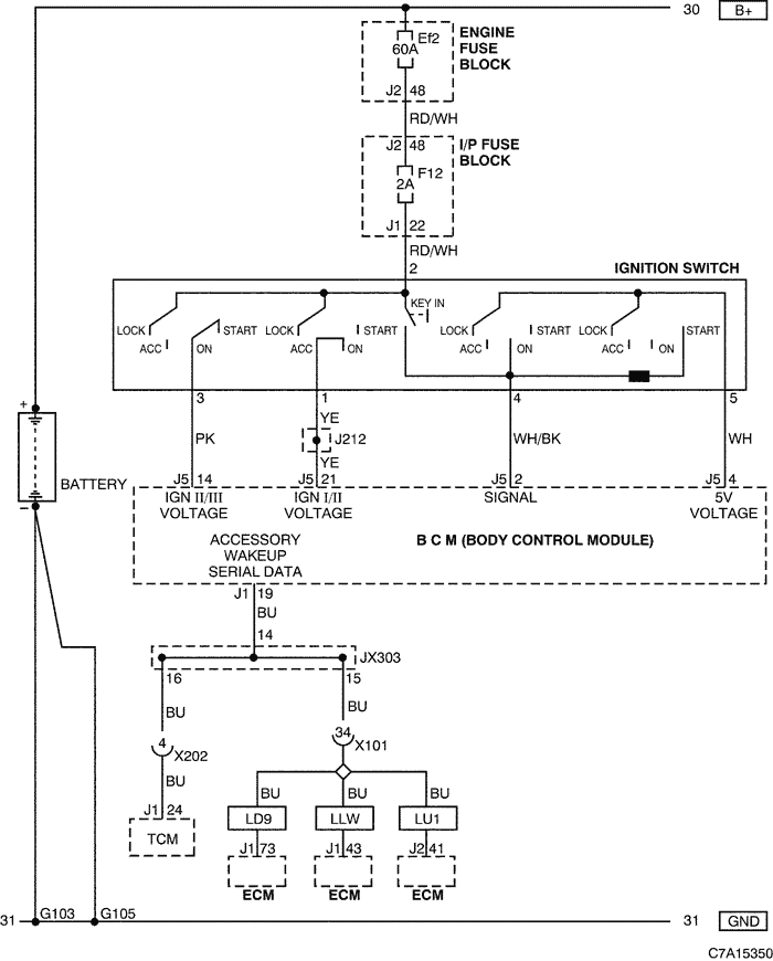
4) IGNITION SWITCH CIRCUIT
a. CONNECTOR INFORMATION
CONNECTOR NO
(PIN NO, COLOR) |
CONNECTING WIRING HARNESS |
CONNECTOR POSITION |
| X101 (36 Pin, Black)
|
Engine - Body |
Behind the Engine Fuse Block |
| X202 (12 Pin, Colorless) |
I.P - Body |
Behind the Audio |
| G103 |
Battery |
Behind the Engine Fuse Block |
| G105 |
Battery |
On the Cylinder Block |
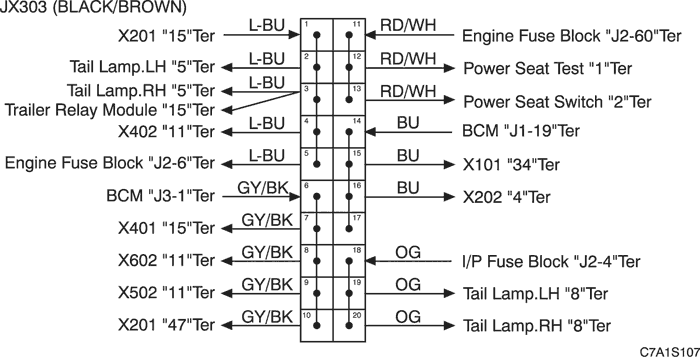
b. CONNECTOR IDENTIFICATION SYMBOL & PIN NUMBER POSITION
c. POSITION OF CONNECTORS AND GROUNDS
d. SPLICE PACK
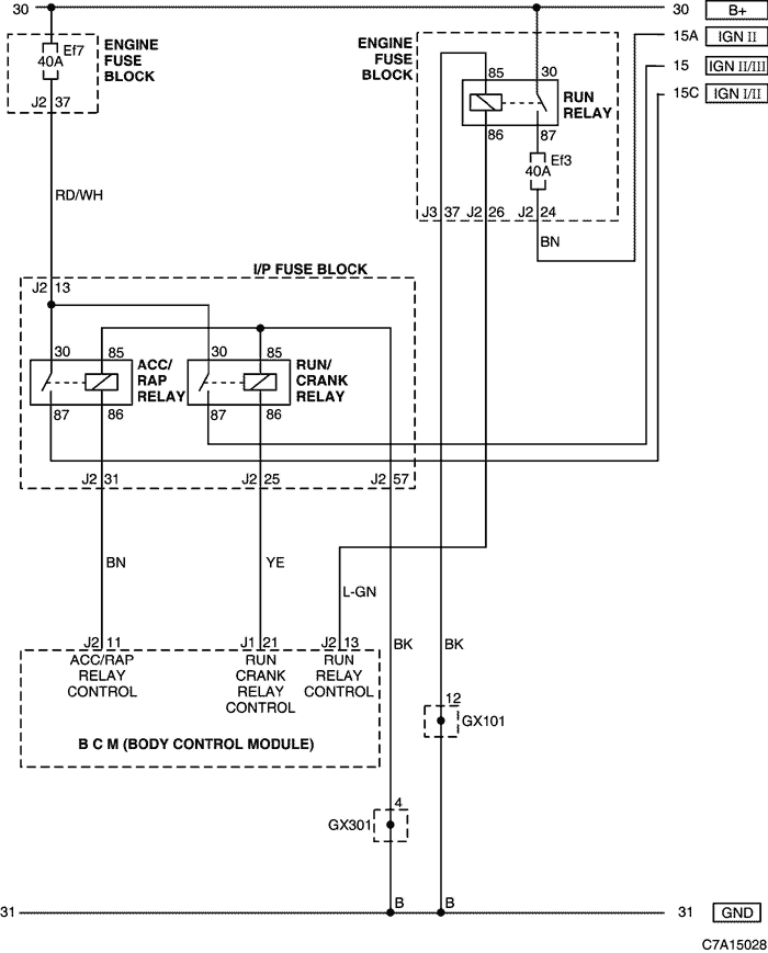
5) POWER MODE CIRCUIT
a. CONNECTOR INFORMATION
CONNECTOR NO
(PIN NO, COLOR) |
CONNECTING WIRING HARNESS |
CONNECTOR POSITION |
| GX101 (Black/Gray) |
Front |
Behind the left HeadLamp |
| GX301 (Black/Gray) |
Body |
Under the right seat cushion |
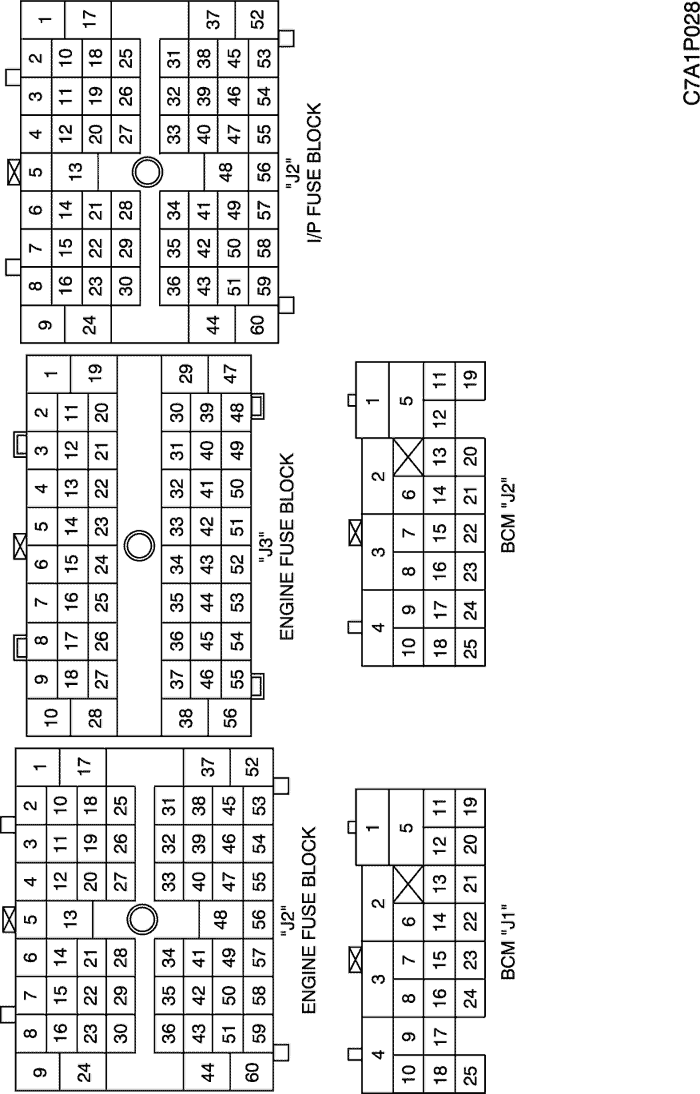
b. CONNECTOR IDENTIFICATION SYMBOL & PIN NUMBER POSITION
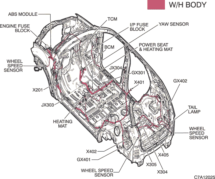
c. POSITION OF CONNECTORS AND GROUNDS
| © Copyright Chevrolet Europe. All rights reserved |